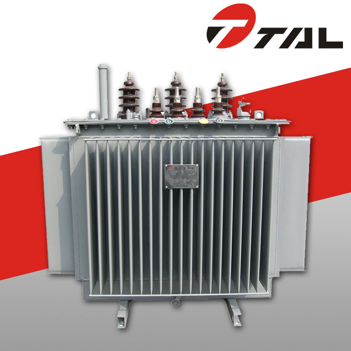
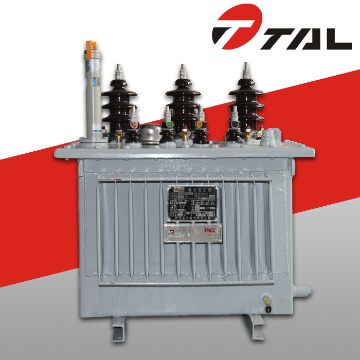
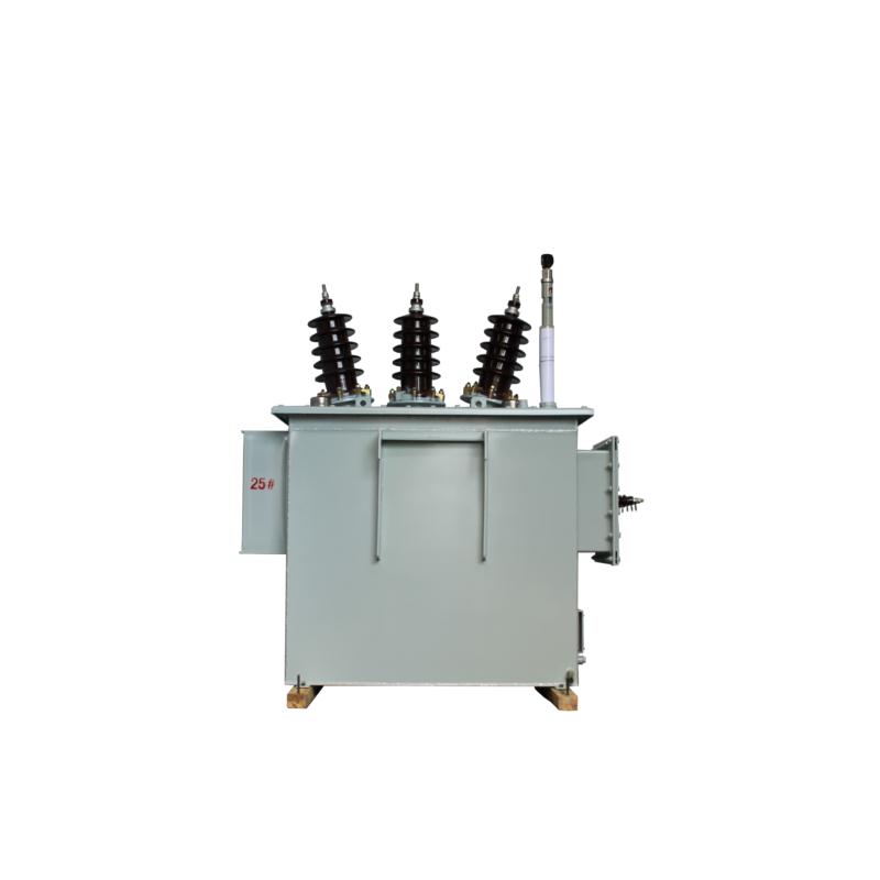
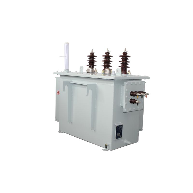
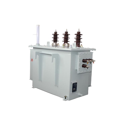
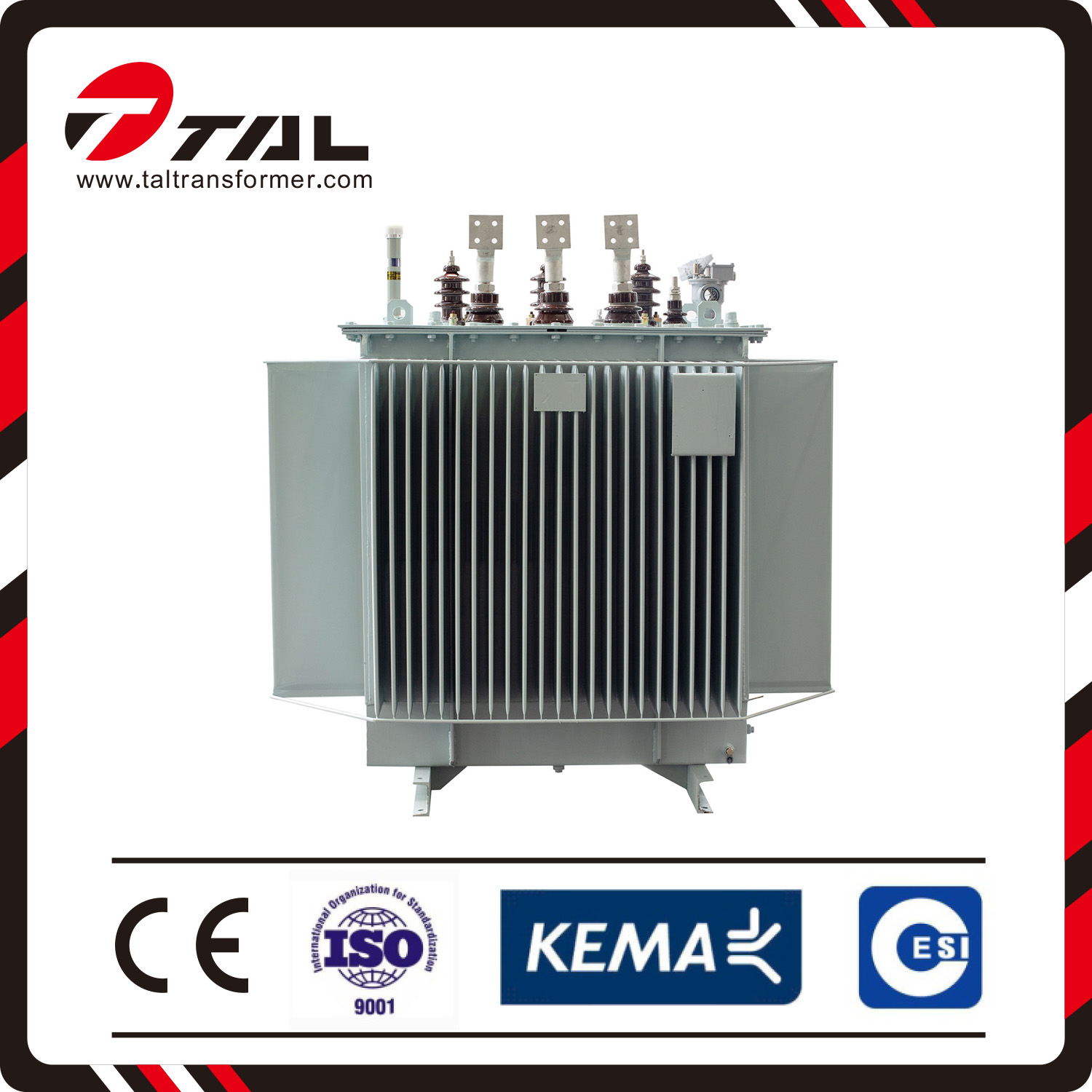
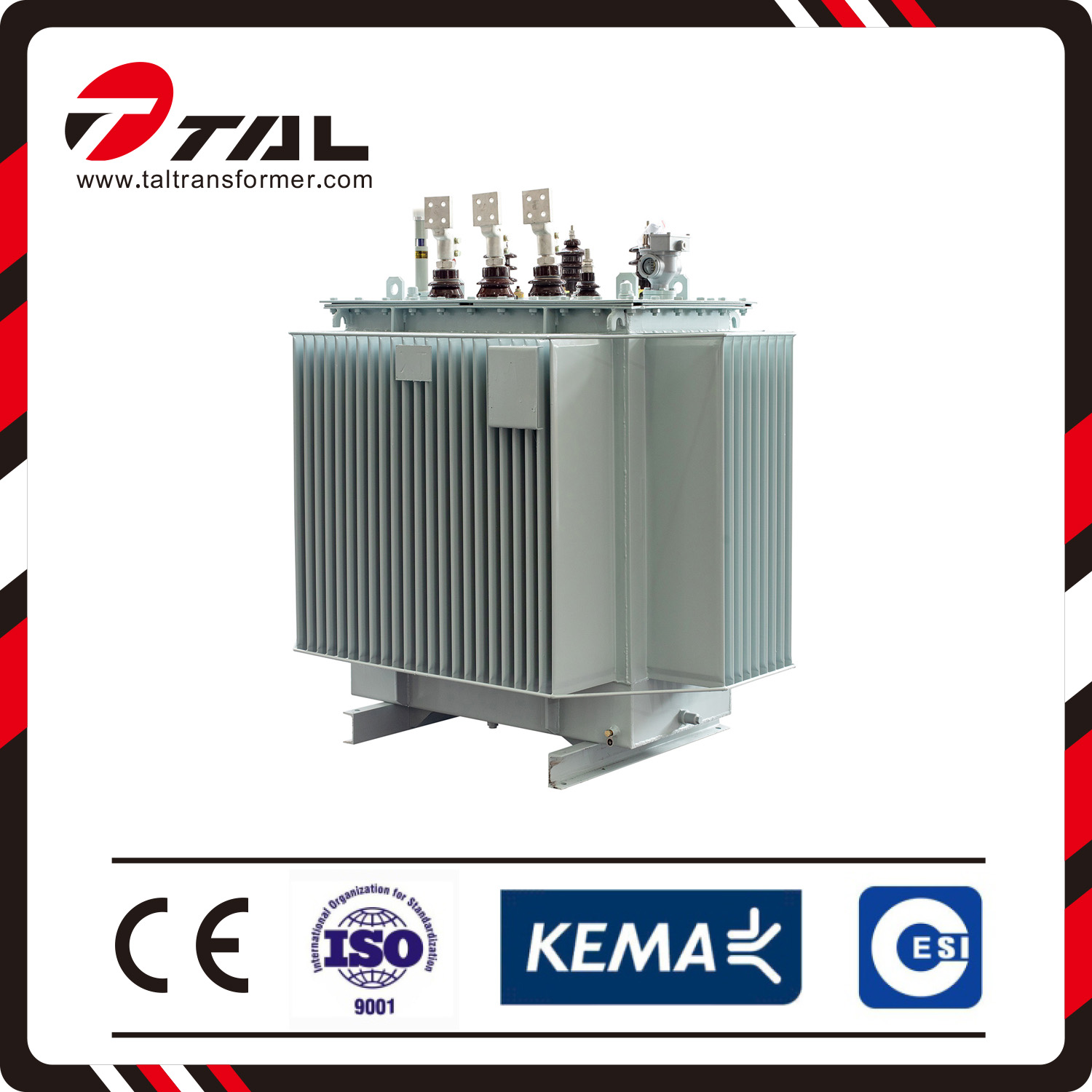
Oil immersed distribution transformers
Oil Immersed Distribution Transformers HV:11KV/22KV/35KV
online service
Advantage of structure
l We employ spiral coil with longitudinal oil path to make a better interior cooling effect;
l We improve the effective support of the coil’s terminal surface to strengthen the anti-short circuit current capability.
l We employ new hoisting structure and body-positioning frames to guarantee that the long distance transport and movement will be more reliable;
l Canceled the oil tank, the wave wings of tank instead of the tubing as a cooling device, corrugated tank is made of high quality cold press sheet on dedicated machine and enhance the reliability of running.
S11-M Type 6~10 kV
Performance parameters
|
Rated capacity(KVA) |
Voltage Combination and tap range |
connection of transformer winding |
No-load loss(W) |
Load loss (W) |
No-load current (%) |
Short circuit impedance (%) |
||
|
High voltage (KV) |
High voltage tap range ( %) |
Low voltage (KV) |
||||||
|
30 50 63 80 100 125 160 200 250 315 400 500 630 800 1000 1250 1600 2000 2500 |
11 10.5 10 6.3 6 |
±5% ±2x2.5%
|
0.4 0.69 |
Yyn0 Dyn11
|
100 130 150 180 200 240 280 340 400 480 570 680 810 960 1150 1360 1640 1960 2310 |
630/600 910/870 1090/1040 1310/1250 1580/1500 1890/1800 2310/2200 2730/2600 3200/3050 3830/3650 4520/4300 5410/5150 6200 7500 10300 12000 14500 19800 23000 |
2.3 2.0 1.9 1.9 1.8 1.7 1.6 1.5 1.4 1.4 1.3 1.2 1.1 1.0 1.0 0.9 0.8 0.8 0.7 |
4 4 4 4 4 4 4 4 4 4 4 4 4.5 4.5 4.5 4.5 4.5 5 5 |
Improved from S9 series product, S11 series product reduces the no-load loss by 30%, no-load electric current by 70~85%, average temperature by 10K, noise level by2~4db, and double the products service life. Even under 20% overloads, it can also work for long period of time.
S11-M Type 20kV
Performance parameters
|
Rated capacity(KVA) |
Voltage Combination and tap range |
connection of transformer winding |
No-load loss (W) |
Load loss (W) |
No-load current (%) |
Short circuit impedance (%) |
||
|
High voltage (KV) |
High voltage taps range (%) |
Low voltage (KV) |
||||||
|
50 100 125 160 200 250 315 400 500 630 800 1000 1250 1600 |
20 22 24 |
±5% ±2x2.5%
|
0.4
|
Yyn0 Dyn0
|
210 290 340 360 430 510 610 730 860 1040 1230 1440 1760 2120 |
1270/1210 2120/2020 2500/2380 2970/2830 3500/3330 4160/3960 5010/4770 6050/5760 7280/6930 8280 9900 12150 14670 17550 |
2.00 1.80 1.70 1.60 1.50 1.40 1.40 1.30 1.20 1.10 1.00 1.00 0.90 0.80 |
6.5 6.5 6.5 6.5 6.5 6.5 6.5 6.5 6.5 6.5 6.5 6.5 6.5 6.5 |
l Energy conservation. Compared with the original S11, the average no-load loss reduced by 20% or more, the no-load current is reduced by 25% or more, operating costs dropped by an average of more than 15%.
l Long service life, transformer core with new core material, and greatly reduce the loss significantly extending the life of the transformer.
l Small footprint, the core is made from high quality cold rolled grain oriented silicon steel sheet; high, low voltage winding made of high quality oxygen-free copper wire and multilayer tact process structure; All fasteners are used special relax treatment, the high mechanical strength, and transformer sizes small, light weight, and the fully sealed tank, can be widely used in various environments.
S13-M Type 6~10 kV
Performance parameters
|
Rated capacity(KVA) |
Voltage Combination and tap range |
connection of transformer winding |
No-load loss(W) |
Load loss (W) |
No-load current (%) |
Short circuit impedance (%) |
||
|
High voltage (KV) |
High voltage tap range ( %) |
Low voltage (KV) |
||||||
|
30 50 63 80 100 125 160 200 250 315 400 500 630 800 1000 1250 1600 |
6 6.3 6.6 10 10.5 11 |
±5% ±2x2.5%
|
0.4 |
Dyn11 Yzn11 Yyn0
|
80 100 110 130 150 170 200 240 290 340 410 480 570 700 830 970 1170 |
630/600 910/870 1090/1040 1310/1250 1580/1500 1890/1800 2310/2200 2730/2600 3200/3050 3830/3650 4520/4300 5410/5150 6200 7500 10300 12000 14500 |
1.8 1.6 1.6 1.5 1.4 1.4 1.3 1.2 1.2 1.1 1.1 1.0 0.9 0.8 0.8 0.7 0.6 |
4 4 4 4 4 4 4 4 4 4 4 4 4.5 4.5 4.5 4.5 4.5 |
|
Dyn11 Yyn0 |
||||||||
S13-M Type 20 kV
Performance parameters
|
Rated capacity(KVA) |
Voltage Combination and tap range |
connection of transformer winding |
No-load loss(W) |
Load loss (W) |
No-load current (%) |
Short circuit impedance (%) |
||
|
High voltage (KV) |
High voltage tap range ( %) |
Low voltage (KV) |
||||||
|
50 100 125 160 200 250 315 400 500 630 800 1000 1250 1600 |
20 22 24 |
±5% ±2x2.5%
|
0.4 |
Dyn11 Yyn0 |
170 230 270 290 340 410 490 580 690 830 980 1150 1410 1700 |
1270/1210 2120/2020 2500/2380 2970/2830 3500/3330 4160/3960 5010/4770 6050/5760 7280/6930 8280 9900 12150 14670 17550 |
2.0 1.80 1.70 1.60 1.50 1.40 1.40 1.30 1.20 1.10 1.00 1.00 0.90 0.80 |
6.5 6.5 6.5 6.5 6.5 6.5 6.5 6.5 6.5 6.5 6.5 6.5 6.5 6.5 |
Welcome to our website! Please send your words at any time in the following form and ask us, we will contact you and provide you with the corresponding service as soon as possible. Please write in English.
Oil immersed distribution transformers
Oil Immersed Distribution Transformers HV:11KV/22KV/35KV
Learn More


